What kind of PMIC does modern design need
Time:2022-05-29
Views:2142
Today‘s power management ICs integrate multi-rail step-down, step-up and LDO voltage stabilization functions with the parameters of each rail, as well as the complex configurable ability to interact with other rails.
Experienced circuit designers know that a stable, accurate and efficient DC power rail is a necessary condition for the reliable and consistent operation of the system. Usually, various voltages are provided by the combination of dc/dc switching regulator (converter) and low-voltage drop regulator (LDO). Each regulator matches the specific voltage, current, accuracy, noise, transient response and other requirements of the power rail it supports.
At the same time, designers also know that even if it is applied separately, a group of independent DC power rails is not enough to meet the complex requirements of today‘s design. From a system perspective, it is not uncommon to use four, six or more DC rails in adjacent physical locations. Since a large number of rails are used, it is important to manage them individually and in groups to ensure that the timing, timing and interrelationship requirements are met (Figure 1).
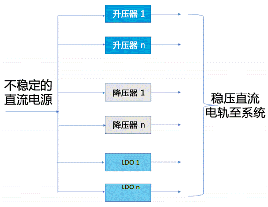
Figure 1: today‘s systems use multiple DC rail arrays provided by step-up, step-down and LDO regulators. Although they have independent outputs, the operation needs to be configured, and the outputs must be coordinated according to the specific requirements of the application to a certain extent.
At this time, power management integrated circuit (PMIC) will play an important role. As the name suggests, this component manages multiple tracks and orchestrates the interactions between tracks to meet the specific needs of the system. Although the earlier generation PMIC mainly managed other dc/dc regulators, today‘s PMIC is integrated with multiple switching converters and LDOS in the same package. Of course, this integration has many significant advantages, including reducing the overall size, reducing the number of passive components required, and realizing the close functional connection between various electric tracks. In addition, the latest generation PMIC is also highly configurable in design, so as to adjust the operation according to the priority of the system it drives.
Application drives PMIC demand
Each electronic product has a power supply and one or more DC rails. Although many applications have similar priorities to some extent, the ranking of priorities and their relative weights determine the differences among these applications. In terms of the management of a single DC track and the relationship, timing and operational requirements between these tracks, there is no optimal PMIC solution that meets all conditions at the same time.
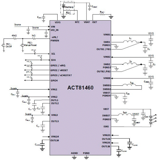
Figure 2: qorvo act81460 is a highly integrated low-power multi rail PMIC that can work without any external active components.
Start with a basic configurable PMIC
Further optimize advanced PMIC
In order to meet the more complex requirements of today‘s systems, PMIC must increase its output range, improve its original DC performance, improve its additional functions, and improve user-defined flexibility. In addition, they must integrate these enhancements with higher-level functional integration to reduce the total footprint of power management functions.
Many parameters that can be adjusted according to the application include:
For example, act88329 PMIC has 4 dc/dc step-down converters using integrated power FET (one of which has bypass function) and 2 LDOS; Each regulator can be configured with a wide range of output voltages (Figure 3). In addition, other functions such as startup time, system level timing, switching frequency, sleep mode and working mode can be configured (or even reconfigured) through the I2C interface without changing the circuit board. Activecips ™ PMIC users want to quickly establish or even change their design settings
through usb-to-i2c dongle and GUI to optimize the performance of their specific design, and simple configurability is a key factor (Figure 4).
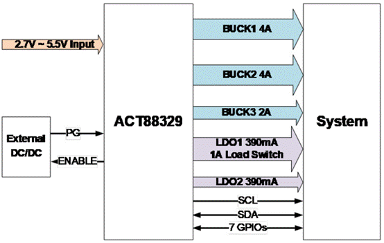
Figure 3: qorvo act88329 PMIC supports configuration of key regulator functions, timing, switching frequency and other operating modes to optimize system level performance.
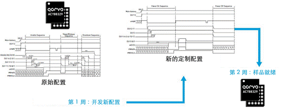
Figure 4: designers can use various parameter configurations to evaluate performance, then use the GUI provided by qorvo and connect to activecips ™ PMIC‘s PCs are easily reconfigured for performance optimization.
This compact 36 pin WLCSP package (2.7mm x 3 mm) device combines high integration and I2C configurability to make the overall solution cover about one third of the floor area of the split alternative solution, and greatly reduce the BOM (Figure 5).
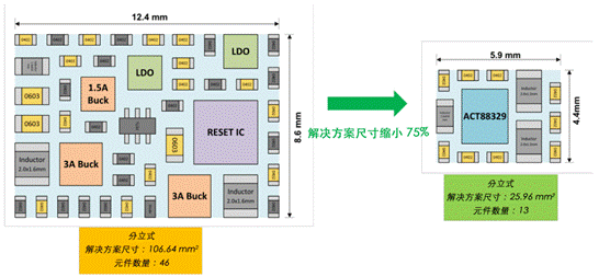
Figure 5: using activecips ™ Another advantage of PMIC series equipment is that it is highly integrated and occupies a much smaller area than the discrete scheme with similar functions.
Evaluation suite, GUI integrates everything
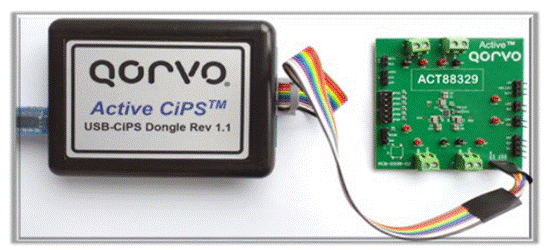
Figure 6: you can use the activecips TM dongle to debug your design and change the PMIC default settings on the board.
Act88329 includes 3 dc/dc step-down converters using integrated power FET and 2 LDOS. Buck1 and ldo1 can be configured as load switches. Buck1 is a fixed frequency dc/dc buck converter in peak current mode, and is optimized for output voltage close to input voltage. The switching frequency can be set to 1.125mhz or 2.25MHz, and only three small components are required to work. Buck2 and buck3 adopt asynchronous constant on-time control architecture, which can optimize load transient response with small output capacitance. Both LDOS require only small ceramic capacitors.

Configuring this flexible multifunction device involves checking and characterizing multiple parameters.
Configuring this flexible multifunction device involves checking and characterizing multiple parameters. This task can be greatly simplified by using the corresponding act88329evk1-101 Evaluation Kit (Figure 7). Only a few standard engineering projects are required to use the suite. (if you don‘t have an electronic load, the power level is low enough (about tens of Watts). Traditional resistive loads can be used, but electronic loads are more versatile). Here is everything you need:
The PC based GUI starts in basic mode, allowing the user to easily change one or more IC settings (Figure 8).
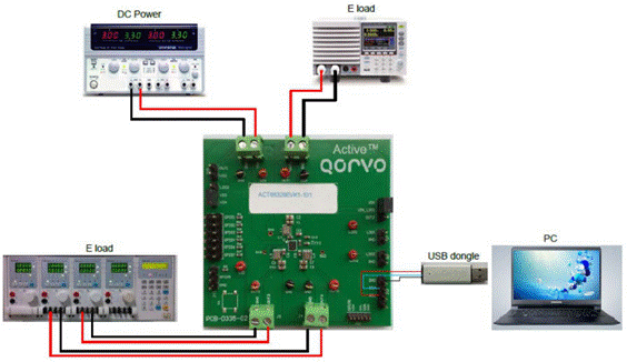
Figure 8: the PC based GUI provided by qorvo is equipped with easy-to-use screens, such as this basic screen for starting the configuration process.
The basic mode is followed by the advanced mode, where the designer can view all available user programmable options (Figure 9).
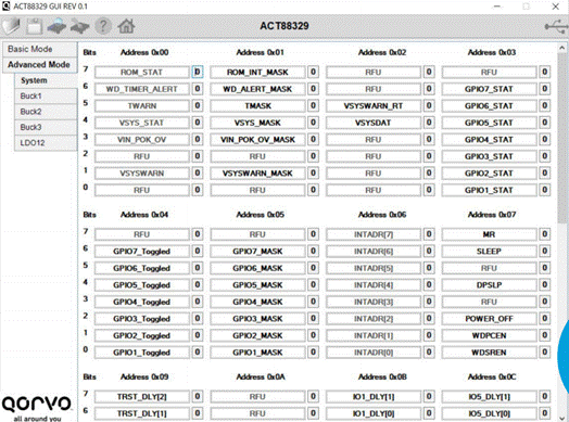
图 9:GUI 的后续屏幕可用于更深入地了解可配置选项。
By using the evaluation suite layout, designers can set, evaluate and modify many operating parameters and modes of these pmics, such as the timing between tracks (Figure 10). The kit also simplifies the measurement of quality factors, such as efficiency under various conditions, which are essential to meet runtime and cooling objectives (Figure 11).
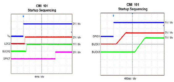
Figure 10: using the Evaluation Kit and associated instrumentation, designers can configure, evaluate, and reconfigure key parameters, such as the relative timing of the various power rails.
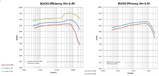
Figure 11: the evaluation kit also simplifies the measurement of important performance indicators, such as the efficiency of various PMIC tracks under different operating conditions. The figure shows buck1 and buck2 of act88329 PMIC.
If designers want to use the suite as the starting point for their own implementation scheme, the evk user guide also provides a complete schematic diagram, BOM and the four-layer layout of their PC board.
Experienced circuit designers know that a stable, accurate and efficient DC power rail is a necessary condition for the reliable and consistent operation of the system. Usually, various voltages are provided by the combination of dc/dc switching regulator (converter) and low-voltage drop regulator (LDO). Each regulator matches the specific voltage, current, accuracy, noise, transient response and other requirements of the power rail it supports.
At the same time, designers also know that even if it is applied separately, a group of independent DC power rails is not enough to meet the complex requirements of today‘s design. From a system perspective, it is not uncommon to use four, six or more DC rails in adjacent physical locations. Since a large number of rails are used, it is important to manage them individually and in groups to ensure that the timing, timing and interrelationship requirements are met (Figure 1).

Figure 1: today‘s systems use multiple DC rail arrays provided by step-up, step-down and LDO regulators. Although they have independent outputs, the operation needs to be configured, and the outputs must be coordinated according to the specific requirements of the application to a certain extent.
At this time, power management integrated circuit (PMIC) will play an important role. As the name suggests, this component manages multiple tracks and orchestrates the interactions between tracks to meet the specific needs of the system. Although the earlier generation PMIC mainly managed other dc/dc regulators, today‘s PMIC is integrated with multiple switching converters and LDOS in the same package. Of course, this integration has many significant advantages, including reducing the overall size, reducing the number of passive components required, and realizing the close functional connection between various electric tracks. In addition, the latest generation PMIC is also highly configurable in design, so as to adjust the operation according to the priority of the system it drives.
Application drives PMIC demand
Each electronic product has a power supply and one or more DC rails. Although many applications have similar priorities to some extent, the ranking of priorities and their relative weights determine the differences among these applications. In terms of the management of a single DC track and the relationship, timing and operational requirements between these tracks, there is no optimal PMIC solution that meets all conditions at the same time.
For example, an Internet of things (IOT) device used for sensing and driving may be in a nearly continuous power on state, located in a remote location, powered by a battery or powered by some form of energy collection device. Since multiple Internet of things (IOT) devices for a given facility (office, factory) are located at remote locations, ensuring long-term performance consistency is critical. In contrast, for consumer electronics, this mainly involves maximizing the running time and battery life, and using small packages, but ultra small packages may not be easy to use. For wearable devices, priority factors include low quiescent current, high efficiency and ultra compact shape.
Therefore, a good PMIC must first have a set of buck, boost and LDO converters that meet the application requirements. For more advanced cases and higher performance, if PMIC can provide DC track and allow designers to customize the performance details of PMIC to match the priority of application, designers can benefit from it. These pmics also face the design reality that it is inevitable to make trade-offs. Assessing and resolving these conflicts is an inherent challenge for designers.

Figure 2: qorvo act81460 is a highly integrated low-power multi rail PMIC that can work without any external active components.
Start with a basic configurable PMIC
Even a basic PMIC can provide functions and features that enhance system performance and simplify design. For example, the qorvo act81460 has an input voltage range of 2.7V to 5.8v and includes a linear battery charger, four dc/dc converters with integrated rate field effect transistors (FETs), three LDOS and three load switches (). Two dc/dc converters are step-down regulators, one is step-up / step-down regulator, and the fourth is high-voltage step-up regulator (capable of providing up to 20V voltage). Each regulator can be configured with a wide range of output voltage through its I2C interface.
This kind of PMIC can not only achieve high integration, but also have many features such as configurable power timing combination, startup timing, output voltage setting, fault monitoring, interrupt control, programmable GPIO options, etc. Through the I2C interface, the firmware can be used to further adjust the pre configured factory default configuration settings.
The three load switches form an interesting additional function. It can be used to turn the power rail on or off, creating a power island for system loads that can be turned off. Minimize power consumption when these loads are not required. In addition, each load switch can be integrated into the start-up sequence of the PMIC, while supporting programmable on and off delay times. Act81460 can also handle hot plug events through a combination of 20V input voltage blocking capability and surge current control at startup.
For more advanced cases and higher performance, if PMIC can provide DC track and allow designers to customize the performance details of PMIC to match the priority of application, designers can benefit from it.
Further optimize advanced PMIC
In order to meet the more complex requirements of today‘s systems, PMIC must increase its output range, improve its original DC performance, improve its additional functions, and improve user-defined flexibility. In addition, they must integrate these enhancements with higher-level functional integration to reduce the total footprint of power management functions.
Aware of this challenge, qorvo has developed a series of highly integrated configurable innovative power supplies (CIPS ™) The solution, as an intelligent system on chip (SOC), simplifies the design process and the final design hardware by eliminating most external components. The solution finally improves the design efficiency and flexibility, greatly reduces the occupied area, reduces the cost in the bill of materials (BOM), improves the system performance and reliability, and shortens the time to market.
Activecips ™ Each device in the series can be configured through I2C interface or nonvolatile configuration matrix.
Many parameters that can be adjusted according to the application include:
• output voltage level.
• power on / off sequence
• timing switch delay time
• GPIO configuration: soft / hard reset, interrupt, configurable timing / control for external power rail, LED heat sink
• changing IC UVLO and ovlo thresholds
• adjust DVS configuration settings
• set up switch FSW
• ldo1 mode setting - ldo/ load switch
• ldo1 mode setting - ldo/ load switch
• multiple sleep modes
For example, act88329 PMIC has 4 dc/dc step-down converters using integrated power FET (one of which has bypass function) and 2 LDOS; Each regulator can be configured with a wide range of output voltages (Figure 3). In addition, other functions such as startup time, system level timing, switching frequency, sleep mode and working mode can be configured (or even reconfigured) through the I2C interface without changing the circuit board. Activecips ™ PMIC users want to quickly establish or even change their design settings
through usb-to-i2c dongle and GUI to optimize the performance of their specific design, and simple configurability is a key factor (Figure 4).

Figure 3: qorvo act88329 PMIC supports configuration of key regulator functions, timing, switching frequency and other operating modes to optimize system level performance.

Figure 4: designers can use various parameter configurations to evaluate performance, then use the GUI provided by qorvo and connect to activecips ™ PMIC‘s PCs are easily reconfigured for performance optimization.
This compact 36 pin WLCSP package (2.7mm x 3 mm) device combines high integration and I2C configurability to make the overall solution cover about one third of the floor area of the split alternative solution, and greatly reduce the BOM (Figure 5).

Figure 5: using activecips ™ Another advantage of PMIC series equipment is that it is highly integrated and occupies a much smaller area than the discrete scheme with similar functions.
Evaluation suite, GUI integrates everything
Incorporating configurable devices into the design raises two related issues. For fixed function equipment, only the data sheet can define the operating parameters and envelope, but the designer must determine the best settings, and then realize these values for configurable equipment in this case. To simplify this process, qorvo provides activecips ™ PMIC series provides evaluation kit and programming electronic dog. This includes all hardware, software, and hooks required to set up, adjust, and evaluate the performance of the PMIC in a given application.
Take act88329 PMIC and Its Evaluation Kit as an example. This 2.18mm x 2.58 mm device in a 30 pin WLCSP package is optimized for not only solid state disk (SSD) and field programmable gate array (FPGA) applications, but also video processors, FPGAs, wearable devices, peripherals and microcontrollers (Figure 6).

Figure 6: you can use the activecips TM dongle to debug your design and change the PMIC default settings on the board.
Act88329 includes 3 dc/dc step-down converters using integrated power FET and 2 LDOS. Buck1 and ldo1 can be configured as load switches. Buck1 is a fixed frequency dc/dc buck converter in peak current mode, and is optimized for output voltage close to input voltage. The switching frequency can be set to 1.125mhz or 2.25MHz, and only three small components are required to work. Buck2 and buck3 adopt asynchronous constant on-time control architecture, which can optimize load transient response with small output capacitance. Both LDOS require only small ceramic capacitors.

Configuring this flexible multifunction device involves checking and characterizing multiple parameters.
Configuring this flexible multifunction device involves checking and characterizing multiple parameters. This task can be greatly simplified by using the corresponding act88329evk1-101 Evaluation Kit (Figure 7). Only a few standard engineering projects are required to use the suite. (if you don‘t have an electronic load, the power level is low enough (about tens of Watts). Traditional resistive loads can be used, but electronic loads are more versatile). Here is everything you need:
• usb-to-i2c "dongle" included
• power supply (3.3v/4a at full power operation)
• oscilloscope (100MHz, dual channel)
• electronic or resistive load (3a minimum current capacity)
• digital multimeter (DMM)
• windows compatible computer with available USB port

Figure 7: using the act88329evk1-101 Evaluation Kit to use the act88329 PMIC requires a standard workbench instrument and the usb-to-i2c interface dongle attached to the kit.

Figure 7: using the act88329evk1-101 Evaluation Kit to use the act88329 PMIC requires a standard workbench instrument and the usb-to-i2c interface dongle attached to the kit.
The PC based GUI starts in basic mode, allowing the user to easily change one or more IC settings (Figure 8).

Figure 8: the PC based GUI provided by qorvo is equipped with easy-to-use screens, such as this basic screen for starting the configuration process.
The basic mode is followed by the advanced mode, where the designer can view all available user programmable options (Figure 9).

图 9:GUI 的后续屏幕可用于更深入地了解可配置选项。

By using the evaluation suite layout, designers can set, evaluate and modify many operating parameters and modes of these pmics, such as the timing between tracks (Figure 10). The kit also simplifies the measurement of quality factors, such as efficiency under various conditions, which are essential to meet runtime and cooling objectives (Figure 11).

Figure 10: using the Evaluation Kit and associated instrumentation, designers can configure, evaluate, and reconfigure key parameters, such as the relative timing of the various power rails.

Figure 11: the evaluation kit also simplifies the measurement of important performance indicators, such as the efficiency of various PMIC tracks under different operating conditions. The figure shows buck1 and buck2 of act88329 PMIC.
If designers want to use the suite as the starting point for their own implementation scheme, the evk user guide also provides a complete schematic diagram, BOM and the four-layer layout of their PC board.
|
Disclaimer: This article is transferred from other platforms and does not represent the views and positions of this site. If there is infringement or objection, please contact us to delete. thank you! |


