- 5V, - 3V, how is the negative voltage generated? Attached circuit analysis and scheme
Time:2022-10-10
Views:1718
Circuit diagram principle of negative voltage generation
In electronic circuits, we often need to use a negative voltage. For example, when we use an op amp, we often need to establish a negative voltage for it. Let‘s take the positive 5V voltage to the negative 5V voltage as an example to describe his circuit.
Usually, when I need to use a negative voltage, I usually choose to use a special negative voltage generation chip, but these chips are expensive, such as ICL7600, LT1054, and so on. Oh, I almost forgot that MC34063 is the most used chip. I don‘t mention the negative pressure generation circuit of 34063 in datasheet. Now let‘s take a look at the two kinds of negative pressure generating circuits that we commonly use in the electronic circuit of the microcontroller.
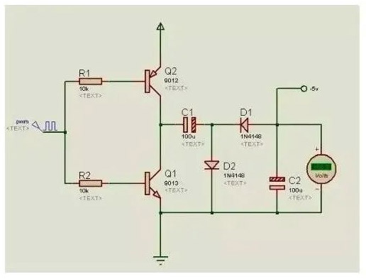
Nowadays, many single chip microcomputers have PWM output. When we use single chip microcomputers, PWM is often not used. It is a good choice to use it to help generate negative pressure.
The circuit above is the simplest negative pressure generation circuit. The original used by him is the least. We only need to provide him with a square wave of about 1kHZ, which is quite simple. It should be noted that the load replacement capacity of this circuit is very weak, and the voltage drop is relatively large after the load is added.
The following circuit is generated due to the above reasons:
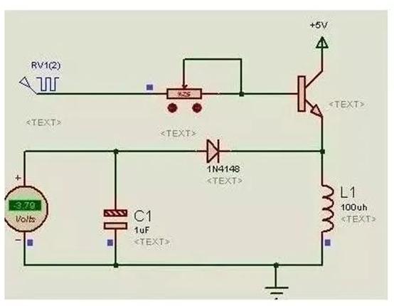
Analysis of Negative Voltage Generation Circuit
Definition of voltage: voltage, also called potential difference or potential difference, is a physical quantity that measures the energy difference of unit charge in electrostatic field due to different potential. Its size is equal to the work done by the unit positive charge moving from point A to point B due to the action of electric field force. The direction of voltage is specified as the direction from high potential to low potential.
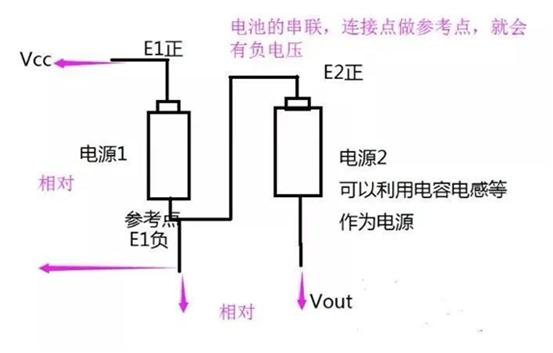
To put it bluntly, the voltage at a certain point is the difference between the potential of a reference point. V some=E some - E parameter. Generally, we take the negative pole of the power supply as the reference point. The power supply voltage is Vcc=E power supply positive - E power supply negative.
If you want to generate a negative voltage, let it have a lower potential relative to the negative pole of the power supply. To be lower, another power supply must be involved. The basic principle is to use the series connection of two power supplies. The positive pole of power supply 2 is connected in series behind the negative pole of reference power supply 1. The negative pole of power supply 2 is the negative voltage.
A negative voltage generation circuit: a new power supply is equivalent by capacitor charging, and the capacitor is connected in series after GND, which is equivalent to power supply 2. A negative voltage is generated.
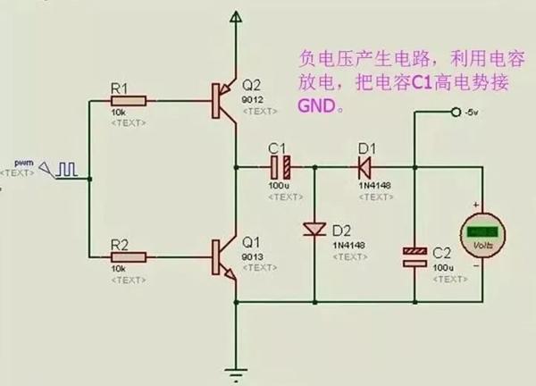
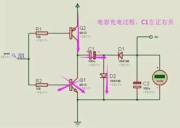
1. Capacitor charging: When PWM is low, Q2 is turned on and Q1 is turned off, VCC charges C1 through Q2, and the charging circuit is VCC-Q2-C1-D2-GND. C1 upper left positive and right negative.
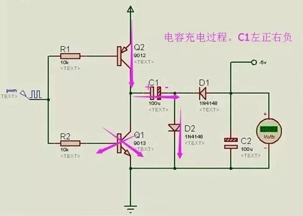
2. Capacitance C1 fully charged
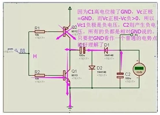
3. The capacitor C1 is used as the power supply, and the C1 high potential pole is connected in series at the reference point. C1 discharge, continuous current from C2, generates negative voltage.
When PWM is low level, Q2 is turned off, Q1 is turned on, C1 starts to discharge, and the discharge circuit is C1-C2-D1, which is actually the process of charging C2. After C2 is charged, it is positive at the bottom and negative at the top. If the potential of VCC is a few volts at 5, it can output a voltage of - 5V.
Scheme for generating negative voltage (- 5V)
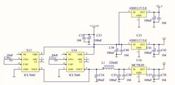
The output capacity of the 7660 and MAX232 is limited, and it is difficult to make oscilloscopes with high-speed operational amplifiers, so Wei Kun has to expand the current with four pieces in parallel.
The first version is a 7660 with two pieces in parallel.
The common DC/DC chip can generate negative voltage, and the voltage accuracy is the same as the positive voltage, and the driving ability is also strong, which can reach more than 300mA.
General switching power supply chips can generate negative voltage. It is impossible to use the PWM output from the switching power supply to push the charge pump, but it can also generate large current at low cost. I do not know how much ripple is required. The ripple of the charge pump after LC filtering is quite small. The 7660 is a charge pump, so the current is very small.
The design of the whole oscilloscope is that the+5V of the digital power supply and the+5V of the analog power supply are powered separately, but how should the digital ground and analog ground be handled?
Digital ground and analog ground must be connected together, otherwise the circuit cannot work.
The ground return current of the digital part cannot flow through the analog part, and the two grounds should be connected at a stable ground reference point.
Meaning of negative voltage
1. Man made regulations. For example, the telephone system is powered by - 48V to avoid electrochemical corrosion of the telephone lines. Of course, it can work to answer the phone in reverse, just because the voltage reference point changes.
2. Communication interface is required. For example, RS232 interface must use negative voltage- 3V ~ - 15V means 1, and+3 ~+15V means 0. This is the protocol when the communication interface was designed, so we can only follow it. PS: Interface chips such as MAX232 have their own charge pumps, which can generate negative voltages by themselves.
3. Provide power rails for (non rail to rail) op amps. The old type op amp has no rail to rail input/output capability. For example, OP07, the input voltage range is always 1V smaller than the power supply voltage range, and the output is 2V smaller. In this way, if the VEE uses 0V, the input voltage must exceed 1V and the output voltage cannot be lower than 2V. This may not meet the design requirements of some circuits. In order to work under the input/output conditions close to 0V, it is necessary to provide negative voltage to the operational amplifier, such as - 5V, so that the operational amplifier can work normally near 0V. However, with the popularity of rail to rail operational amplifiers, this situation is increasingly rare.
4. This is a self destructing circuit with Chinese characteristics. Generally speaking, the protection circuit inside the chip is not protected against negative voltage, so as long as the current is slightly high and the voltage is not very high, the chip can be successfully destroyed.
|
Disclaimer: This article is transferred from other platforms and does not represent the views and positions of this site. If there is any infringement or objection, please contact us to delete it. thank you! |


