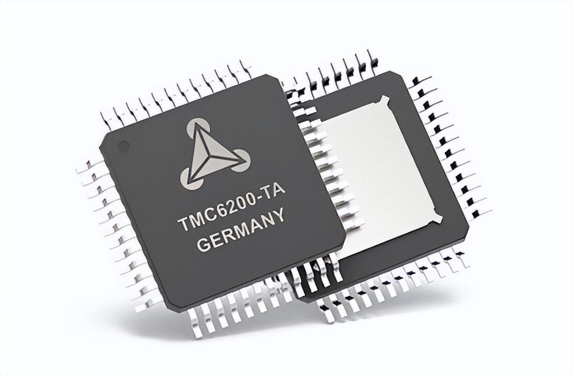
Selection and Basic Principle of DC Brushless Motor Driver Chip
Time:2022-12-05
Views:1493
Brushless DC motor is a typical mechatronics product, which is composed of motor actors and drivers. The motor rotor winding resistance adopts the three-phase star interface, which is very similar to the three-phase AC motor. In order to check the rotation of the generator rotor, a phase sensor is installed in the motor. The controller is composed of output power electronic components and integrated circuit chips. How to select DC brushless motor driver chips?

1. Universal chips are generally used for low-end products of LED displays, such as indoor single color and dual color screens. The most common general-purpose chip has the functions of 8-bit latch, string shift register and tri state output. Each large circuit can output the current of 35mA non constant current power supply.
2. Large output current: At this stage, the popular constant current source LED driver chip has a large output current of 90mA per channel. The maximum value of stable current output by each channel is more meaningful for the display. Under the condition of automatic white balance, each channel is required to output constant current power supply current.

3. Number of output channels of constant current power supply: There are two types of output channels of constant current power supply: 8-bit and 16 bit. Nowadays, 16 bit is popular. Its key advantage depends on the reduced chip size, which is conducive to the routing of LED driver boards (PCBs), especially for LED driver boards with small point spacing.
4. Precise current output: one is the current error between the same chip channels; The other is the output current error between different chips. Precision current output is a very important main parameter, which is very harmful to the symmetry of LED display. The larger the deviation is, the worse the homogeneity is, and it is difficult to make the led transparent screen achieve automatic white balance. At present, the bit to bit current deviation of popular constant current source chips is generally within ± 3%, and the chip to chip current deviation is within ± 6%.
5. Data information mobile digital clock: it determines the transmission rate of data information and is an important indicator value that endangers the upgrade speed of the display. As a large capacity display device, it indicates that the refresh rate should be above 85Hz to ensure a stable interface (no flashing sense of the scanner). Moving the digital clock with higher data information is the basis for the display to obtain a high refresh rate interface. At present, the mobile clock frequency of chips driven by popular constant current sources is generally above 15-25MHz.
Basic principle of DC brushless motor driver chip:
Four dmos transistors are integrated in the dc brushless motor driver chip to form a standard h - type driver. According to the power circuit of the battery charging pump, the two switch tubes of the upper bridge arm are provided with grid voltage control working voltage, and the power circuit of the battery charging pump has an output power of 300 kHz. The second battery charging pump power circuit can be generated by connecting external capacitors at pins 1 and 11. The larger the external capacitor, the faster the charging rate of the capacitor battery input to the switch tube grid voltage, the less time the working voltage rises, and the higher the output power. Pin 2 and 10 are connected to the DC brushless motor synchronous motor, and the current direction should be from pin to pin 10 during forward rotation; The current should be oriented from pin 10 to pin 2 when flipping. The current verification output pin 8 can be connected with a grounding resistor to output the overcurrent condition according to the resistor. The over-current threshold set for the internal maintenance power circuit is 10A. When it exceeds this value, the output will be automatically blocked and the output will be automatically repaired regularly. If the overcurrent delay time is long, the overtemperature maintenance will turn off all outputs. The overtemperature data signal can also be output according to pin 9. When the junction temperature reaches 145 degrees, pin 9 has an output data signal.
|
Disclaimer: This article is transferred from other platforms and does not represent the views and positions of this site. If there is any infringement or objection, please contact us to delete it. thank you! |


