Ultra low distortion audio pan can amplifier
Time:2023-06-15
Views:939
Author: Chau Tran
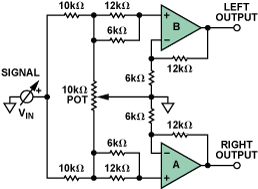
The audio "pan pot" circuit shown in Figure 1 continuously changes the position of the mono audio signal between the left and right stereo channels according to the potentiometer setting. Low cost and low distortion are important considerations for audio circuits. The AD82731 dual channel low distortion differential amplifier uses internal gain setting resistors to ensure excellent matching between the two channels. No external components are required, and each channel is configured with two high-performance amplifiers with a gain of 3. In the audio range, Total harmonic distortion is less than 0.0007%.
Although the circuit can be built separately, integrating amplifiers and resistors on a single chip can bring advantages to circuit board designers, including improving specifications, reducing PCB area, and reducing production costs.

Figure 1. Audio pan amplifier.
In this circuit, the signal is distributed between two amplifiers using a series connected 10 k Ω resistor. A potentiometer with a grounded cursor is inserted between two in-phase inputs. The combination of potentiometer and 10 k Ω resistor presents a light load, and most power sources can be easily driven. The gain configuration of the amplifier is 3. When the potentiometer cursor is located at either end, one input is grounded, so there is no signal directly passing through the corresponding output. The other input sees V at/2, so its output is 1.5 × When V is in the middle, the input of both amplifiers is V at/3, so the output of each amplifier is V. Therefore, by moving the cursor (mechanical or electronic), the signal level is between 0 and 1.5 × Continuous variation within the V range in a single channel, 1.5 × V is 0 on another channel, so for the listener, the source seems to move from one channel to another through the sound field. This allows the obvious source of images or sound to be placed anywhere between the left and right speakers.

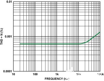
Figure 2. Relation between Total harmonic distortion, noise and frequency.
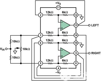
Figure 2 shows the Total harmonic distortion and noise in the audio range. The error increases with frequency, but the total error is still less than 0007.20% at 0 kHz. Figure 3 shows the connection to the IC

Figure 3. Wiring diagram.
|
Disclaimer: This article is transferred from other platforms and does not represent the views and positions of this site. If there is any infringement or objection, please contact us to delete it. thank you! |


