Working principle of three-phase PWM motor driver A3936
Time:2023-08-27
Views:732
Brushless DC motors have the advantages of simple structure, reliable operation, and convenient maintenance of AC motors, as well as the high efficiency and good speed regulation performance of DC motors. They are increasingly widely used in industrial control, instrumentation, aerospace and other fields. A3936 is a new generation of dedicated control/driver chip for three-phase brushless DC motors launched by Allegro Corporation.
.jpg)


Features and functions of A3936
1.1 Main Features
A3936 is a new type of DMOS three-phase PWM motor driver produced by Allegro Company in the United States. It mainly includes commutation logic and power drive circuits, and can complete the speed regulation and forward and reverse control of brushless DC motors by giving control voltage signals and directional control logic signals. In addition, the A3936 also has functions such as internal undervoltage locking, cross current protection, and overheating protection, making it very convenient to use. In addition, A3936 also has a continuous output of ± 3 A/50 V; And it has four programmable continuous flow working modes. Including slow mode, fast mode, and two mixed modes; Simultaneously capable of low-power synchronous rectification control. The typical output resistance of A3936 is 0.55 Ω when pulling current; The typical value during current injection is 0.35 Ω. The A3936 chip is equipped with undervoltage locking, cross current protection, and overheating protection functions internally, as well as sleep and idle modes, as well as brakeable functions and dead zone settings.
1.2 Pin Introduction
The A3936 chip adopts a 44 pin PLCC packaging style, and its pin arrangement is shown in Figure l. The functions of each pin are as follows:
.jpg)
Pins 1, 2, 11, 12, 13, 22, 23, 24, 33, 34, 35, 44 (GND): Ground terminal;
Pins 3, 4, 5, 6, 7, 8 (HA, HB, HC): Signal input terminal for HALL component of brushless DC motor;
Pin 9 (VDD):+5 V power supply;
Pin 10 (REF): Reference voltage VREF input terminal, PWM duty cycle can be controlled by controlling this voltage;
Pin 14 (BRAKE): Brake control terminal. When this pin is at high voltage, the current in the brushless DC motor will be instantly released, causing the motor to suddenly stop rotating; During normal use, this pin is connected to a low level;
Pin 15 (SENSE): Sampling resistor RS pin, its value is generally taken as 0.1 Ω. The sampling resistance and VREF can determine the load current of the motor.
Pin 16 (SR): Synchronous rectification input, effective at high levels;
Pins 17, 2l, 28 (OUT): brushless DC motor A, B, C phase drive output terminal;
Pin 18 (HBIAS): Negative pole of HALL component;
Pins 19 and 26 (VBB): Load power supply;
Pins 20 and 25 (LSS): Connected to the load power supply ground through sampling resistor RS;
Pin 27 (TACH): Speed output, generally not used when suspended;
Pin 29 (VCP): Charging capacitor connection end, should pass through 0.22 μ F/50 V capacitor connected to VBB;
Pin 30, 3l (CPl, CP2): Charge pump capacitor connection terminal, both should pass through 0.22 μ F/100 V capacitor connection;
Pin 32 (SLEEP): Sleep mode logic control input, enter sleep mode when low level input;
Pin 36 (OSC): Oscillation signal connection terminal, which can be connected to VDD through a 51k Ω resistor;
Pin 37 (VREG): Rectifier decoupling end, should be externally connected with 0.22 μ F/50V decoupling capacitor;
Pin 38 (DIR): Direction control logic input, low level for clockwise rotation, high level for counterclockwise rotation;
Pin 39 (ENABLE): Enable control logic input;
Pin 40 (EXTMODE): External PWM control mode logic input terminal. When using external PWM control mode, if a high level is input, it is in slow current decay mode; If the input level is low, it is in fast current decay mode;
Pin 41 (BLANK): Dead band logic control input terminal; If a high level is input, the dead time is 12/fosc; If the input level is low, the dead time is 6/fosc;
Pins 42, 43 (PFD): PFD logic control input, the combination of the two can be used to determine which freewheeling control mode to use.
Working principle of A3936
2.1 Power on control law
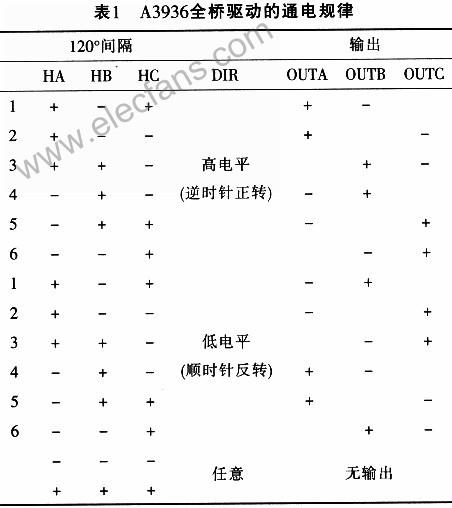
The A3936 has a power logic switch unit driven by a full bridge and a signal processing unit for position sensors, which can be used to control the sequence and time of energizing each phase winding on the motor stator. The power logic switching unit of full bridge drive can allocate the power of the power supply to each phase winding on the motor stator in a certain logical relationship, so as to generate continuous torque for the motor. The signal processing unit of the position sensor can convert the position signal of the motor rotor into an electrical signal, in order to provide correct commutation information for the power logic switch circuit and control the commutation of the motor stator winding. At the same time, the steering of the electric motor is also controlled by the 38 pin directional control logic. The logical relationship between the three is listed in Table 1.

In Table l, in the HALL sensor section: "+" represents high level; - "indicates low level; Output part: "+" indicates forward power on; "-" indicates reverse power on. 2.2 Load current regulation
The load current can pass through the fixed low level inside A3936 (typical value is 24 when using a 4MHz crystal oscillator μ s) PWM circuit for adjustment. When the H-bridge operates normally, the motor winding current rises until it reaches the threshold, which is determined by the following equation:

When the threshold is reached, the logic circuit will close the H-bridge, and the load current will continue to flow under the action of induced electromotive force. The flow path during the continuous flow is determined by the slow/mixed continuous flow mode and synchronous rectification mode.
2.3 Continuous flow control mode
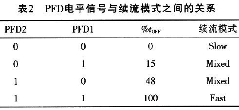
The level signals of input pins PFD1 and PFD2 of A3936 determine the different freewheeling modes of the load current during overcurrent shutdown or PWM chopping. According to the different levels of PFDl and PFD2 signals, A3936 has four continuous current control modes: slow mode, fast mode, and two mixed modes. The different continuous current modes determine different load current waveforms. The relationship between PFD level signal and freewheeling mode is listed in Table 2.

2.4 Synchronous rectification mode
When the SR pin of A3936 is at high level, synchronous rectification mode is enabled, and the load current is selected according to the control logic for continuous current. During the continuous current period, the synchronous rectification control circuit opens the corresponding MOSFET transistor, so that the load current can continue to flow through the MOSFET transistor at the same time, thereby reducing the conduction voltage during continuous current and reducing the conduction loss. At the same time, the synchronous rectification control circuit also considers dead zone protection, which can prevent the bridge arm from passing through directly.
Application circuit of A3936
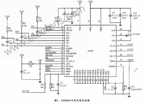
The A3936 brushless DC motor drive integrated circuit is very easy to use due to its high integration and few peripheral components. The peripheral circuit connection diagram is shown in Figure 2.

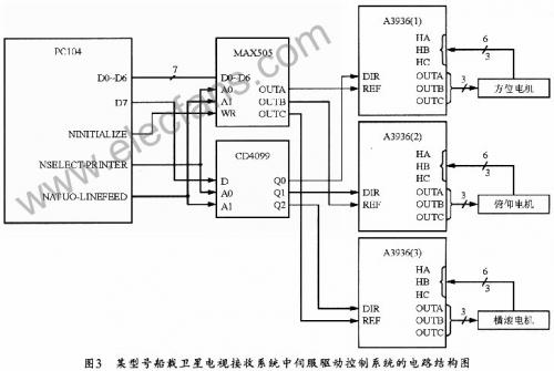
After the circuit is connected, the continuous current control mode and synchronous rectification mode can be set (or not). Afterwards, simply provide the direction of motor rotation (determined by the control logic of 38 feet) and the speed of rotation (determined by the voltage of 10 feet REF) to complete the control of the motor. The servo drive control of a certain type of ship borne satellite TV receiving system requires servo drive control of the horizontal, pitch, and roll directions of the receiving antenna. The control core uses a PC104 computer and uses its I/O port (25 pin parallel port) to control the A3936. Due to the digital output of PC104 and the need to control three brushless DC motors, this design adds a 4-way 8-bit D/A conversion circuit MAX505 and an 8-bit gate switch CD4099. MAX505 is used to control the motor speed; CD4099 is used to control the steering of the electric motor. The circuit structure diagram is shown in Figure 3.

The PC104 standard parallel port has 12 output bits and 5 input bits, among which D0-D6 in the 8-bit data bits DO to D7 are the data sent to MAX505, which can be used to control the speed of brushless DC motors after D/A conversion. A0 and A1 are the address lines of MAX505, which can be controlled by pins 14 and 17 of the PC104 parallel port, and are used to determine which output end of VOUTA, VOUTB, or VOUTC should be converted from DO to D6. WR is the write control terminal, controlled by the 16 pins of the PC104 parallel port, but after the data write operation is completed, the WR terminal must be set to 1. D7 represents the direction of rotation (D7 is 0 for clockwise rotation; D7 is 1 for counterclockwise rotation). D7 is usually connected to pin 3 of CD4099, which allows CD4099 to send information in this direction to the corresponding output terminal based on the address data of A0 and A1, thereby controlling the corresponding A3936 and ultimately achieving directional control of the corresponding brushless DC motor. When it is necessary to control the brushless DC motor, simply write the control words to the corresponding addresses (0X378, 0X37A) to achieve control of the motor‘s rotation direction and speed.
4 Conclusion
The unique continuous current control mode of A3936 allows the brushless DC motor to obtain different load current waveforms under different loads, thereby ensuring high control accuracy. Synchronous rectification mode can reduce the conduction voltage and power consumption during continuous current. Due to the compatibility of A3936 devices with computer interfaces and the simple and flexible control methods, it has high application value.
|
Disclaimer: This article is transferred from other platforms and does not represent the views and positions of this site. If there is any infringement or objection, please contact us to delete it. thank you! |


