How to design a reasonable reverberation in ADI DSP
Time:2024-02-01
Views:334
Author: Terry Yuan
Abstract: This article provides a detailed description of the requirements, principles, and implementation process of reverberation. On the one hand, it can help everyone understand some basic knowledge of reverberation effects, and on the other hand, engineers can refer to these models to apply to their own products, so as to design algorithms that are more suitable for their own products.
The demand source for DSP reverberation
When sound waves propagate indoors, they are reflected by obstacles such as walls, ceilings, and floors, and each time they pass through the reflection, they are absorbed by the obstacles. After the sound source stops producing sound, sound waves need to undergo multiple reflections and absorption indoors before finally disappearing. Therefore, we can feel that after the sound source stops producing sound, there are still several sound waves that mix and continue for a period of time, which is the phenomenon of sound continuity that still exists after the indoor sound source stops producing sound. This phenomenon is called reverberation, and this period of time is called reverberation time.
When performing, reverberation is an extremely important component in order to achieve a high-quality musical effect. With the increasing demand for acoustic related equipment, people‘s demands for sound quality in music are also increasing. The main implementation methods for reverberation include physical simulation, sampling reverberation, and manual reverberation. Due to the huge computational cost, physical simulation is difficult to implement in practical scenarios and is rarely used. The implementation of sampling reverberation is simple, but the flexibility is not enough and the types are relatively limited. However, artificial reverberation has a small computational cost and is easy to implement, so it is widely used in practical applications. Of course, the disadvantage is that it is not as realistic as the first two, but it can support ordinary tuning, mixing, and performance needs without any problems. The following will introduce the concept, application, and implementation of reverberation in DSP.
The definition and advantages of DSP reverberation
DSP Reverb is a technology that uses digital signal processing technology (DSP) to achieve reverberation effects. Reverberation refers to the phenomenon of reflection, scattering, and attenuation of sound waves in indoor or other enclosed spaces, which can make sound more spatial, deep, and wide. In audio processing and music production, reverberation is very important as it can make the sound more natural, rich, and three-dimensional. It has the following advantages:
• Flexibility: It can easily adjust and change reverberation parameters, such as delay time, attenuation rate, room size, etc., to adapt to different application scenarios.
• Real time processing: Through real-time processing technology, audio signals are processed in real time to achieve reverberation effects.
• High quality: can provide high-quality reverberation effects, making the sound more natural and realistic.
• Resource saving: can save valuable audio processing resources, such as CPU, memory, etc.
In summary, DSP reverberation has a wide range of applications in music production, recording, broadcasting, gaming, movies, and other fields. Through DSP reverberation technology, we can create more rich, three-dimensional, and natural sound effects. When it comes to reverberation, another concept we need to know is echo. Echoes are delayed reflections in one direction, while reverberation is multiple delayed reflections in multiple directions. In the principle of software reverberation, what we can see can be basically divided into the following three types:
• Echo type: an echos system constructed with multiple echoes, and the number of echoes is controlled by oneself according to specific types.
• Pulse response type (IR type): commonly used for on-site collection of various models, and achieving good output results by convolving with the back sound source.
• Schroeder&Moore class: It is a hybrid model structure.
For some mainstream reverberation types on the market, such as room reverberation, hall reverberation, panel reverberation, church reverberation, spring reverberation, etc., their implementation principles can be achieved using the above three methods. At present, these common types of reverberation are mainly used in the engineering of mixers or mixers to enhance special effects, increase the atmosphere, spatial sense, and three-dimensional sense of music.
ECHO class reverberation system
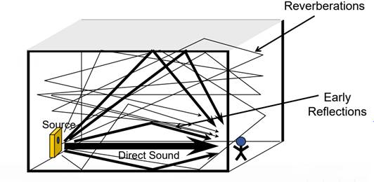
When it comes to echo type reverberation systems, it is necessary to mention the Comb Filter reverberator, which is simply understood as the process of sound continuously colliding and producing echoes in space. Similarly, on the player side, what we need to play is actually a sound source and a process of adding it to countless subsequent echoes, abbreviated as a comb filter reverberator. Here we need to establish a mathematical model, and the following figure (Figure 1) represents a simple room reverberation model:
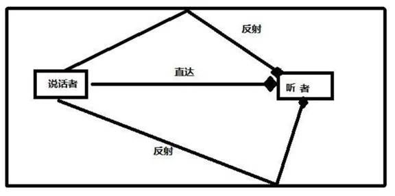
Figure 1 Room Sound Model
From the figure, it can be seen that the reflection effect of the house is influenced by the size of the room and the reflection intensity. If the room is large enough and the sound-absorbing material is very good, it will result in almost no reflection inside the room. On the contrary, the reflection will be stronger. In room architectural design, the Sabine formula is commonly used for estimation, while the standard for reverberation intensity is generally RT60. Referring to this physical model, we can perform a series of formula derivations in the design process of comb filters, such as:
Assuming that the signal spoken by the speaker is x [n] and the signal received by the listener at a certain moment is y [n], what content does y [n] contain?
Y [n] should be x [n]+reflection 1+reflection 2
How is reflection represented? It should be a delay of x [n]. We assume a delay of m, so reflection 1 should be x [n-m], but we should also consider the attenuation during reflection, which is the reflection effect of the house mentioned above. Assuming attenuation is a, reflection 1 should be expressed as x [n - m] * a
So, y [n]=x [n]+a * x [n-m]+a ^ 2 * x [n-2m]+a ^ 3 * x [n-3m]
Simplify the sum and use difference or z variation to obtain the difference equation: y [n]=ay [n-m]+x [n]
Through the above formula derivation, the model structure diagram and time-domain and frequency-domain performance can be obtained as shown in Figure 2.
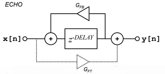
Figure 2 Block diagram of the model
In the time domain, as an equally proportional (feedback attenuation coefficient depends on the designed attenuation formula) attenuation model, it exhibits a periodic decreasing pattern, as shown in Figure 3:
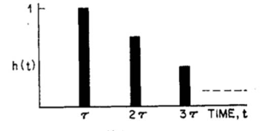
Figure 3 Changes in unit impact response over time
In the frequency domain, the system has a periodic response to frequency and has both maximum and minimum values. In this way, we will obtain a comb like waveform, as shown in Figure 4, which is also known as a comb filter.
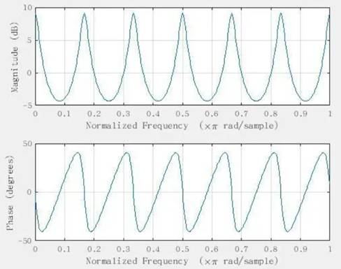

Figure 4 Spectrum and Phase Representation
From this, we can design a simple algorithm based on such a model. In DSP chips, its computing power is not very high and the storage space is not very large. However, sometimes when we need to select some products that are more useful in echo type reverberation systems, such as lightweight low-power electronic products, we need to have some reverberation edge effect, and we can achieve it in this way. For other products with higher standards and less power consumption sensitivity, we will use the two methods introduced below to achieve better results.
IR class reverberation system
For simulating real-life reverberation, imagine if we were talking face-to-face in a room, because the reflection of sound in the room is ubiquitous, during the process of communication, the initial part of the sound will directly enter our ears, and its energy is at its highest. Subsequently, through various reflections, the energy of the sound is attenuated and slowly enters our ears. This time and energy performance is like pulses, so it is described here as one of the reverberation types of pulse response. So, how can we achieve this realistic reverberation effect in implementation?
In the field of computer science, we often generate IR files based on different reverberation characteristics, and we can also obtain specific spatial reverberation through recording and other methods. Due to some reverberation, it is very difficult to implement the algorithm and has certain specific conditions. However, when we need this reverberation background again, we need to use it.
In terms of implementation, we usually perform convolution operations through specific IR files and the original audio source, and the calculation formula and method of convolution are relatively complex. For the convenience of everyone‘s understanding, it can be imagined that the input signal is multiplied with IR to achieve the reverberation effect of IR in the input signal.
In the implementation of DSP, similar to the feature reverberation we often see in some upper computer software, these IR files will be stored in our Flash in various ways and may have multiple model1, model2, model3, and so on. Take specific files out and perform convolution operations inside the DSP to output them, which is commonly seen in certain types of reverbs in music devices.
Schroeder&Moore class reverberation system
The ECHO class reverberation mentioned earlier may have some imperfections after the comb filter design is completed. In fact, from the amplitude spectrum and phase spectrum, it can be seen that the amplitude spectrum is not flat enough. Therefore, under conditions with large resonance peaks and transients, the sound performance it brings is heavily colored, and the phase change is not constant. Therefore, Schroeder made significant improvements to reverberation technology, which was mentioned in two papers titled "Colorless" Artistic Reversion 1961 and "Natural Sounding Artistic Reversion 1962.". In response to the insufficient echo density, multiple parallel combinations of comb filters have been added, and an all-pass filter has also been added. Because the spectrum of an all pass filter is a straight line that does not affect any frequency and only has some group delay effects, it can be used to achieve the effect of eliminating strong coloring. At the same time, due to the increase in echo density, the system will approach the real effect more closely, as shown in the following figure (Figure 5):

 This article provides a detailed description of the requirements, principles, and implementation process of reverberation. On the one hand, it can help everyone understand some basic knowledge of reverberation effects, and on the other hand, engineers can refer to these models to apply to their own products, so as to design algorithms that are more suitable for their own products.

Figure 5 Real reverberation model diagram
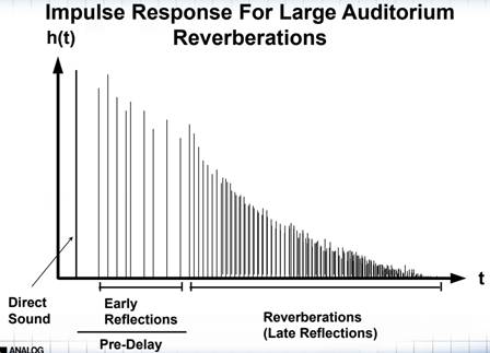
Its pulse response can be roughly described as a graph shown in the following figure (Figure 6):

Figure 6 Pulse response model diagram
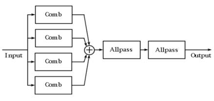
The block diagram of its model is shown in the following figure (Figure 7):

Figure 7 Schroeder pulse response model diagram
It is not difficult to see from the above model that the superposition of four comb filters will greatly increase the echo density, thus compensating for the problem of ECHO class echo density being too rare. In Schroeder‘s concept, at least 1000 echoes per second are required to meet the basic requirements, and the delay of each echo cannot be the same, which can lead to consistency in the time domain of the echoes produced by four comb filters, thus losing its significance. After stacking the comb filters, multiplication is performed by connecting two all pass filters to further increase echo density while reducing metallic sounds.
In the parameter selection of Comb, the delay ratio is generally chosen at 1:1.5, and it is advisable to choose delay times without common factors. Common factors can cause overlap in certain areas, and the size of G (attenuation coefficient) should be reasonably designed. Generally, the calculation is based on the D value and RT60 to ensure that the size is within a reasonable range. In the selection of all pass filters, the delay should be as low as possible (1-5ms), and a gain value between 0.5 and 0.77 would be more appropriate.
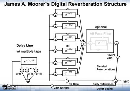
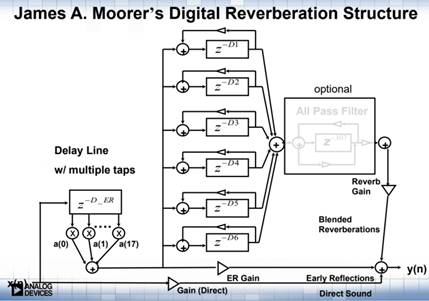
The Schroeder reverberation algorithm is relatively simple and can also achieve a very good effect. However, with the development of the Schroeder algorithm, there are also some areas that can be improved, such as the pre combing and pre delay modules in the above figure (Figure 6). If you want to achieve more realistic effects, in the early stages of reflection, it is not entirely possible to design according to the Schroeder model. We need to add APF and Pre delay modules, or consider whether we can add more Combs to obtain more echo density Can the backend APF be nested and used. On the basis of Schroeder, Moore‘s digital reverberation model was also born. The following figure (Figure 8) shows the Moore pulse response model:

Figure 8 Moorer pulse response model diagram
The Moore algorithm model roughly divides a reverberation into three stages: direct reverberation, early reverberation, and late reverberation. Early reverberation was simulated by adding front-end feedback and FIR, while low-pass filters were added to simulate the attenuation effect of high pass in the air. The back-end was increased to 6 Comb groups and nested use of APFs. With the increasing demand for audio related products, reverberation has become a basic requirement for audio devices. So what parameter adjustments are there in reverberation? How should we choose DSP to design a reasonable algorithm in ADI‘s DSP? Next, we will conduct in-depth analysis on the specific parameter adjustment of reverberation and the selection of a reasonable DSP design algorithm for ADI.
Common parameters of reverberation
At present, creating a professional level reverb requires setting many parameters, some of which are essential, while others are gradually added according to specific needs. Professional renderings generally include some parameters as shown in Figure 9:

Figure 9: Relevant parameters of reverberation
• Reverberation time: Digital reverberators that can realistically simulate natural reverberation have a complex set of programs. Although there are many adjustable technical parameters, the adjustment of these parameters will not be more natural than the original effect, especially the reverberation time (depending on the pre delay time, as well as the determination of attenuation rate and convergence).
• Pre delay time: Among the many parameters on the reverberation effect device, pre delay time is a relatively important point. The so-called pre delay time refers to the time interval between the direct sound reaching the human ear and the first reflected sound. In mixing, the selection of pre delay time is somewhat related to our baseline time. The calculation method of the benchmark time is generally to divide 60 seconds by the value of the music BPM (depending on the delay time after the direct sound and the time of FIR).
• High frequency roll off: This parameter is used to simulate the absorption effect of air on high frequencies in natural reverberation, in order to produce a more natural reverberation effect. The adjustable range for general high-frequency mixed descent is 0.1~1.0. When this value is high, the reverberation effect is also closer to natural reverberation; When this value is low, the reverberation effect is clearer (depending on the order of the low-pass filter and the design of the cutoff frequency).
• Diffusion: This parameter can adjust the growth rate of the reverberation array density, with an adjustable range of 0~10. When its value is high, the reverberation effect is relatively rich and warm; When its value is low, the reverberation effect is more open and remote (depending on the selection of the D value of the Comb Filter and the increasing value of echo density).
• Acoustic Array Density: This parameter can adjust the density of the acoustic array. When its value is high, the reverberation effect is relatively warm, but there is obvious acoustic staining; When its value is low, the reverberation effect is deeper and the cut sound staining is weaker (depending on the number of Comb Filters).
• Frequency modulation: This is a technical parameter because the sound density of electronic reverberation is sparser than that of natural reverberation. In order to make the reverberation sound smoother and more coherent, it is necessary to modulate the delay time of the reverberation sound array. This technology can effectively eliminate segment cracking in delayed sound arrays and increase the softness of reverberation (depending on the delay time of the Comb Filter).
•Reverberation type: The natural reverberation array in different rooms also varies greatly, and this difference cannot be expressed by one or two parameters. In digital reverberators, different natural reverberations require different programs. The available options generally include S-Hall, L-Hall, Room, Random, Reverse, Plate, Spring, etc. The reverberation in the small hall and lobby rooms belongs to the natural reverberation effect; Steel plate and spring reverberation can simulate the treatment effect of early mechanical reverberation.
• Dry wet ratio: the ratio of dry sound signal to reverberation signal, adjusting the proportion of direct sound and reverberation signal components.
It is not difficult to see from the subsequent development of these parameters that more and more adjustment options are involved. Therefore, it is very important for designers to choose the appropriate parameters and types to build the products they want.
Selection of DSP and Reverb Types
In practical production applications, choosing the type of reverberation is not just about choosing the most perfect type. In fact, many times the application cannot meet this condition. The more complete the reverberation type, the greater the demand for DSP memory space and computing power. However, many cost budgets are not sufficient, or the working environment has requirements for power consumption and other aspects of the product, so we cannot choose such a high complexity reverberation.
For example, if customer A needs to make a lightweight guitar pickup, the main purpose of the pickup is to pick up sound. Of course, in order to enrich the effect, we may need to adjust the EQ of high, medium, and low frequencies and add a reverb. At this time, choosing an ECHO reverb is much better than choosing a MOORER reverb. From the perspective of cost control and power consumption, although ECHO classes are not as good as Moore classes, they are already sufficient for performance. Complex ones can be achieved by picking them up and sending them to the effector or amplifier.
When choosing, it is recommended to choose the most suitable product based on the type of product, including cost, packaging size, and power consumption.
Basic Implementation of ADI DSP in ECHO Algorithm
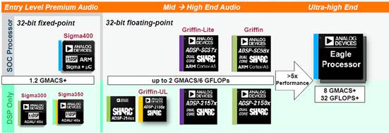
As is well known, ADI is quite competitive in audio DSP, and from its Sigma to Sharc class DSP, it is used in various audio electronic products. The comparison table for ADI SigmaDSP product selection is shown in the following figure (Figure 10):

Figure 10 Comparison Table of Product Selection for SigmaDSP
The following figure (Figure 11) is a comparison table of ADI Sharc DSP product selection:

Figure 11 Comparison Table of Product Selection for SharcDSP
The products of ADI SigmaDSP are fixed-point digital signal processors, while SharcDSP is a fully floating-point digital signal processor. Full floating-point DSPs can handle complex reverbs, while SigmaDSPs are generally used to handle simpler reverbs. The following will demonstrate the application implementation of ECHO type reverberation on DSP. Currently, reverberation mainly requires a lot of memory space and there are many delays.
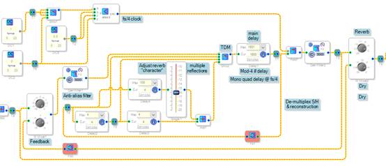
Implementation in ADAU1701 and ADAU1761:

Figure 12 Implementation of ECHO class reverberation in ADAU1761
From the above figure (Figure 12), it can be seen that the direct sound is directly transmitted as a dry sound to the output end. The left and right channels of the sound source are combined to reduce memory space and computational power consumption. Three delay lines are used to create reverberation space, which is then transmitted to the backend for low-pass filtering, achieving high-frequency roll off. This approach can achieve a certain amount of reverberation effect, but the echo density is insufficient, and gain adjustment, as well as diffusion and frequency modulation, cannot be achieved. It is suitable for some lightweight product applications. We usually implement it directly through code in SharcDSP, such as the implementation of ECHO class echo below:
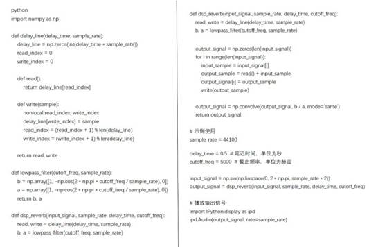
Create a DSP reverb effector. The following figure (13) is an example code of a simple DSP reverb effect implemented using Python and the NumPy library:

Figure 13 Python implementation of DSP reverberation effect (horizontal version)
The code shown in the above figure (Figure 13) implements a basic DSP reverberation effect, including delay lines and low-pass filters. We can adjust the delay time and cutoff frequency as needed to change the effect of reverberation. It should be noted that this example uses Python‘s NumPy library to process digital signals and needs to be run in an environment that supports audio playback (such as Jupyter Notebook or Python scripts).

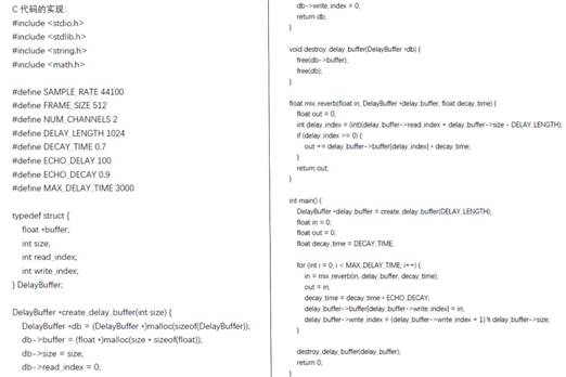
Figure 14 Implementation of ECHO class reverberation effect in C language (horizontal version)
The code shown in the above figure (Figure 14) is a simple DSP reverb effect implementation, which is programmed in C language. The code mainly involves the following operations:
• Defined some constants, such as sampling rate, frame size, number of channels, delay length, and decay time;
• Defined a structure called DelayBuffer to implement a delay buffer;
• Created a file called create_ Delay_ The buffer function is used to create a delay buffer;
• Defined a name called destroy_ Delay_ The buffer function is used to destroy the delay buffer.
In the main function, a delay buffer is first created, and then a loop is entered to simulate the input, processing, and output processes of the signal. In each loop, the signal is input into the reverberation effect processing, and the processed signal is output. Meanwhile, the decay time is also constantly decreasing. Finally, when the delay time reaches its maximum value, the loop ends and the delay buffer is destroyed. On our Sharc platform, after running the Framework, we can import this part of the code and import the audio stream to obtain an ECHO class reverb effect.
If you need a more advanced and user-friendly Schroeder&Moore class reverberation system, you can obtain it through open-source frameworks such as Sox, Freeverb, and Tonic. The complete algorithm will be relatively long, and you need to refer to it online.
summary
|
Disclaimer: This article is transferred from other platforms and does not represent the views and positions of this site. If there is any infringement or objection, please contact us to delete it. thank you! |


