Grounding for noise reduction in electronic systems
Time:2024-03-04
Views:264
When there is EMI, RFI, or electrical pulse interference caused by welding machines, variable speed drives, appliances, etc. in the grounding system, they will generate common mode noise between the neutral line and ground, which may affect electronic equipment.
The National Electrical Code (NEC) allows for the installation of isolated grounding sockets (IG), where there is no connection between the magnetic yoke and the grounding terminal. Yoke is the metal frame behind the socket used to secure the device to the outlet box.
The ideal goal of an IG system is to provide low neutral to ground voltage in the AC input of electronic devices, which can prevent noise from passing through logic circuits and damaging the processed data.
After proper installation, the voltage (noise) from the neutral wire to the isolation ground should be lower than the voltage from the neutral wire to the metal conduit.
But there is nothing isolated in this grounding arrangement. The isolation device grounding conductor (EGC) provides a low impedance path for the grounding fault current between the socket grounding terminal and the neutral point in the service equipment or the secondary of a separately derived system (such as an isolation transformer). Isolation type EGC (instead of conduit) is the safe grounding of electronic equipment - the way for fault current to return to the source. The green insulator with vertical yellow stripes identifies the isolated EGC.
The metal frame of the socket must be grounded. The framework of the socket has a separate grounding connection, which is connected to the general grounding system through metal conduits, insulated (green wire), or bare equipment grounding conductors operating together with circuit conductors, or other wiring methods used as EGC.
NEC allows for the isolation of EGC passing through multiple sub panels without the need to connect to the grounding bus. In fact, isolating EGC may terminate at sub panels where the noise reaches an acceptable level.
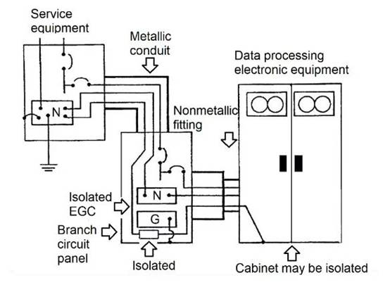
Figure 1 shows an isolated grounding system that supplies power to data processing (DP) electronic devices.

Figure 1 The IG system that supplies power to DP equipment.
The metal raceway is grounded through a connection to the service equipment casing. The isolated EGC connected to the neutral point of the service equipment passes through the downstream distribution board and terminates in the electronic equipment cabinet. NEC allows the use of non-metallic conduit fittings to isolate equipment cabinets from conduits containing power conductors.
When electronic device manufacturers specify isolation grounding for devices, they usually do not provide isolation grounding terminals for this purpose. Connect only one grounding terminal to the AC power supply, chassis, cabinet, and zero reference. In this case, the safety grounding (green or bare wire) should not be connected to the grounding terminal. The equipment cabinet should be isolated from the ground and other metals in contact with safety grounding, in order to maintain the isolated EGC as the path for grounding fault current.
The power supply of electronic devices should not share a common branch circuit that supplies power to noise generating devices. For example, supplying power to a copier with a motor and heater from the same circuit can inject high-frequency noise into the grounding system, disrupting the operation of electronic devices. If the copier requires an IG system because it has a microprocessor based circuit, it should be connected to a separate branch. Not to mention supplying power to coffee machines, clocks, radios, vacuum cleaners, drills, and other noisy devices.
An important fact is that IG does not always enhance device performance.
Shielded isolation transformer
Sometimes, the distance between the main service equipment and the electronic equipment is too long, resulting in an excessively long EGC between the electronic equipment and the power ground. Long wires will have relatively high impedance, reducing the fault current required to open circuit breakers and fuse, and increasing the time it takes for fuses and circuit breakers to clear faults. Furthermore, recalling that the noise current passes through the EGC cycle, the enhanced impedance will generate a larger noise voltage.
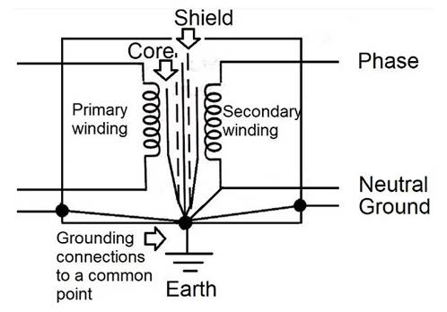
One method to shorten EGC and reduce the aforementioned impact is to install shielded isolation transformers near electronic devices and their distribution boards. The shielding isolation transformer has good insulation between the primary and secondary windings, excluding the main service equipment with neutral grounding and restoring grounding at the secondary winding.
Connecting the EGC to a closer new ground will provide a better return path for fault currents and reduce common mode noise.
Figure 2 shows a schematic diagram of a shielded isolation transformer.

Figure 2. Shielded isolation transformer for electronic devices.
Practical arrangements for reducing common mode noise
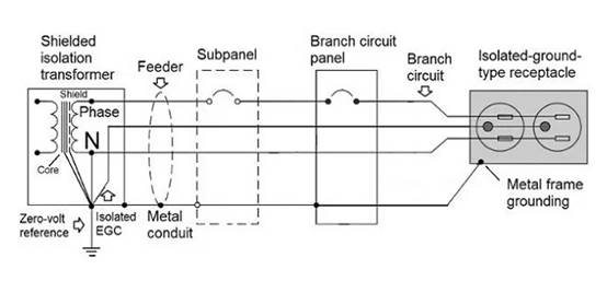
Figure 3 shows a practical arrangement of using the IG principle to power inserted electronic devices, such as a set of personal computers and peripheral devices. This arrangement should provide an acceptable level of common mode noise suppression.

Figure 3 Use an IG socket to ground.
The power supply is a shielded isolation transformer located near the distribution board, reducing wire length and noise. The shielding layer of the transformer can suppress a large amount of high-frequency noise.
According to NEC, isolation transformers are qualified for independent derived systems - the neutral point is not transmitted from input to output - and a neutral grounding connection is required on the low-voltage side. This key provides zero voltage reference for electronic devices.
The isolated EGC is directly connected to the neutral point of the isolation transformer to the grounding point through a conduit from an isolated grounded socket (supplying power to electronic devices). EGC can pass through sub panels without being connected to the grounding bus of the device‘s metal frame. Connect the metal conduit carrying the isolated EGC to the casing at both ends. NEC requires all wires originating from the secondary winding (phase, neutral, isolated EGC, and green when in use) to operate in the same conduit.
When the grounding system of peripheral devices and computers is connected through a data cable shielding layer, this arrangement can reduce trouble.
Signal reference structure in data processing room
Signal Reference Structures (SRS) are commonly used to establish grounding references for computer devices and electronic devices placed in control rooms, thereby reducing common mode noise.
SRS equalizes the ground potential from DC to the megahertz range. It provides many parallel grounding paths to avoid resonance situations. When the length of the grounding path matches a multiple of the quarter wavelength of the usage frequency, resonance occurs, causing the lead to appear as an open circuit.
SRS can be in the form of a signal reference plane or a signal reference grid. The signal reference grid is more economical and usually uses a support structure of the elevated floor of the room.
The elevated floor is composed of a metal longitudinal beam grid supported by a metal base. Floor tiles are a specific part of the floor that falls into the longitudinal beams. The top of the ceramic tile is made of low conductivity material, providing isolation for the equipment cabinet directly placed on it, but allowing for the release of static electricity generated by personnel. The bottom of the ceramic tile is made of copper mesh, which has good contact with the supporting structure. The metal longitudinal beams are bonded together to form a ground plane.
Below the elevated floor are branch circuit conductors, power lines, communication, data, grounding, connection and interconnection cables, wire and plug connections, and sockets related to electronic equipment.
NEC allows the use of SRS to connect to the grounding conductor (green or bare wire) provided to electronic devices. Connect the pipes, steel structures, and other metal components entering the room directly or through grounding rings to the metal longitudinal beams.
Figure 4 shows a typical signal reference grid layout in elevated floors. In the figure, SRG refers to the signal reference grid.
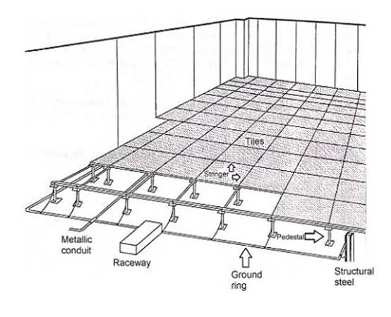
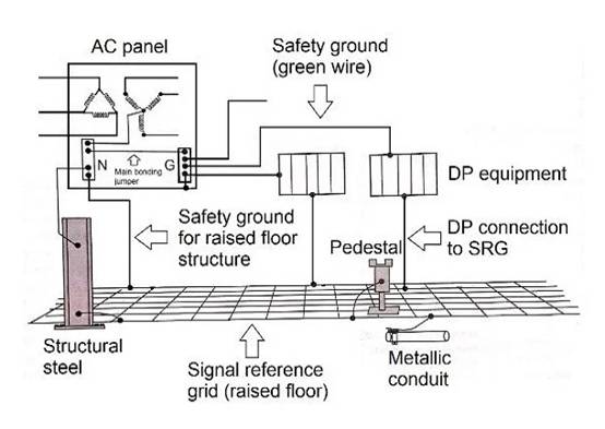

Figure 4 Typical SRG using elevated flooring.
The cabinet in the room can be grounded to a single point, usually through a grounding rod in the AC panel that supplies power to the cabinet. The AC grounding bar is a single point grounding of the power cord and the cabinet.
A good choice is to place the power supply inside the room - such as an isolation transformer - and ground it inside or around the room. The computer power center is a complete component that provides branch circuits for data processing equipment, with control, monitoring, and alarm functions.
Short leads will isolate the secondary neutral point of the transformer, ground all signals, and connect the cabinet to the signal reference grid.
Figure 5 shows a typical grounding connection in the data processing room.

Figure 5. DP device connected to AC power ground and SRG.
Overview of Noise Reduction and Grounding in Electronic Systems
NEC allows isolated equipment grounding conductors to provide noise free, zero voltage reference in electronic systems with microprocessors.
Isolation EGC extends from the neutral/ground connection point (main connection jumper) on the service equipment or individual dispatch source to the electronic equipment or isolation socket.
The isolated EGC (green wire with yellow stripes) must be installed in the same conduit as the phase wire, neutral wire, and safety grounding wire (green wire) conductor, and can pass through the sub panel without connecting to the grounding bus. Any approved wiring method must ground the metal casing of the IG socket.
Advantageously, the electronic equipment room receives power from specialized transformers (such as isolation transformers). Isolation transformers can be shielded and useful for common mode noise attenuation. Its main function is to provide separate energy sources in close proximity to electronic devices and isolate them from other energy sources within the premises.
|
Disclaimer: This article is transferred from other platforms and does not represent the views and positions of this site. If there is any infringement or objection, please contact us to delete it. thank you! |


