What are the main technical parameters of a power amplifier?
Time:2024-03-15
Views:239
What are the technical parameters of audio amplifiers? How can we understand these parameters as ordinary users? Next, the editor of HD Era Network will popularize the relevant knowledge of amplifier parameters for everyone, and also share with you how to understand the meaning behind these parameters.
 (2) Intermodulation distortion
1. Output power
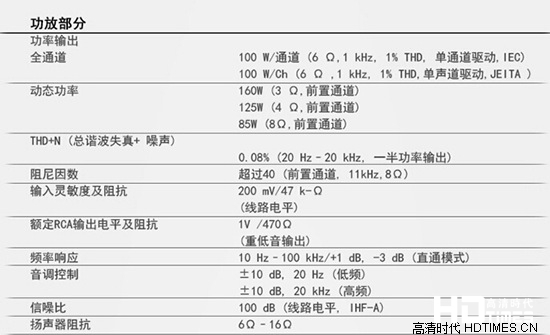
The unit of output power is W. Due to different measurement methods, some different names have emerged, such as rated output power, maximum output power (dynamic power), music output power, and peak music output power. Some manufacturers who mix fish and fish often use this to confuse users.

Power amplifier parameters
Peak power refers to the maximum music power that an amplifier can output when its volume is adjusted to its maximum within allowable distortion conditions.
Rated output power refers to the maximum output power when the distortion is less than a specified value, also known as maximum useful power. Usually, the peak power is greater than the music power, and the music power is greater than the rated power. Generally, the peak power is 5 to 8 times the rated power.
2. Frequency response
Indicates the unevenness of the level gain within the operating frequency range of the power amplifier. The flatness of the frequency response curve is expressed in decibels (dB).
The lower the decibel value, the flatter the frequency response curve, the smaller the distortion, and the higher the performance of the speaker. The frequency response of home Hi Fi amplifiers is generally between 20 Hz and 20 kHz, with a range of 1 dB. The wider the frequency response range, the better.
3. Total harmonic distortion
It indicates that during the operation of the power amplifier, due to inevitable oscillations or other resonances in the circuit, the second and third harmonics are superimposed with the actual input signal. The output signal at the output end is not simply the same component as the input signal, but also a signal that includes harmonic components. The comparison between these excess harmonic components and the actual input signal is expressed as a percentage, which is Total Harmonic Distortion (THD).

4. Distortion
The ideal amplifier should amplify the input signal without any changes. In fact, compared with the input signal, the amplified signal of the power amplifier produces varying degrees of distortion, which is called distortion. Expressed as a percentage, the smaller the value, the better. The distortion of power amplifiers includes harmonic distortion, intermodulation distortion, cross distortion, clipping distortion, transient distortion, transient intermodulation distortion, etc.
1) Harmonic distortion
Harmonic distortion is a type of distortion caused by nonlinear components in power amplifiers. This distortion causes the audio signal to generate many new harmonic components, which are superimposed on the original signal, forming a waveform distorted signal. The total harmonic distortion is obtained by adding up the distortion caused by each harmonic, and its value is commonly expressed as the percentage of the ratio of the root mean square value of all harmonics in the output signal to the effective value of the fundamental voltage.
The main methods to reduce harmonic distortion are:
(1) Apply an appropriate amount of negative voltage feedback or negative current feedback;
(2) Select amplification components with high fT, small NF, and good linearity;
(3) Try to improve the consistency of transistors in each unit circuit as much as possible;
(4) Using Class A amplification method and selecting excellent circuit programs;
(5) Improve the power reserve of the power supply and improve its filtering performance.

Two or more signals with different frequencies are modulated with each other after passing through amplifiers or speakers to produce sum and difference frequencies, as well as the combination of various harmonics to produce sum and difference frequency signals. The nonlinear distortion formed by these newly added frequency components is called intermodulation distortion.
Usually, two high and low frequency signals with amplitudes in a certain proportion (usually 4:1) are mixed into the circuit, and the root mean square value of the newly generated nonlinear signal is measured as the percentage of the amplitude of the original higher frequency signal to measure intermodulation distortion, which can be expressed as the percentage of the intermodulation product level to the rated signal level. The larger this value, the greater the intermodulation distortion.
Common methods to reduce intermodulation distortion include:
(1) Using electronic frequency division to limit the working bandwidth of amplification circuits or speakers;
(2) Install a high pass filter at the input end of the audio amplifier to eliminate sub low frequency signals;
(3) Choose pipes or circuit structures with good linearity.
3) Transient distortion
Transient distortion is an important indicator of modern acoustics, which reflects the ability of power amplifier circuits to maintain tracking of transient jump signals, hence it is also known as transient reflection. A high fidelity system that experiences transient distortion results in a lack of hierarchy and transparency in the output music signal. It is widely recognized as the culprit that affects the sound quality of stone machines, leading to "transistor sound" and "metal sound", and people attach great importance to this.
The commonly used methods for improvement include:
(1) Control the open-loop gain and negative feedback of the amplifier to around 50dB and 20dB respectively;
(2) Select high fT tubes, with the front stage using tubes with an fT greater than 100MHz, and the final stage power tube having an fT greater than 20MHz. Try to broaden the open-loop frequency response of the circuit and increase the negative current feedback of each stage, eliminating the negative feedback of the large loop. At present, some power amplifiers (such as the Bell JA-100) do not involve loop negative feedback in their final stage expansion circuits, and one of their purposes is to do so;
(3) Adopting a fully complementary symmetrical circuit to increase the working current of the power output stage, and adding a buffer amplification stage before the output stage to improve the transient response of the circuit;
(4) Cancel the phase lag capacitor and change the lag compensation to lead compensation, that is, no lag compensation capacitor is needed, and a small capacitor of appropriate capacity is connected in parallel on the feedback resistor of the large loop;
(5) Appropriately increase the static current of the input stage, increase its dynamic range, and set a low-pass filter in its input circuit to eliminate high-frequency clutter signals above 80kHz, preventing high-frequency interference signals from causing instantaneous overload of the input stage.

4) Distorted communication interface
Communication interface distortion is caused by the feedback of the back electromotive force of the speaker through the circuit.
The methods to improve this distortion include:
(1) Reduce the number of circuit stages and appropriately increase the static working current of the circuit;
(2) Select suitable speakers to make the damping coefficient more reasonable;
(3) Using high capacity and high-quality power transformers, and appropriately increasing the capacity of the filtering capacitor, parallel small capacity CBB capacitors on the filtering capacitor.
5) Cross distortion
Cross distortion, also known as cross over distortion, is mainly caused by the nonlinear conduction of the power transistor in Class B push-pull amplifiers. Especially in the case of small currents, the output current produces nonlinear distortion at the junction, and the smaller the signal amplitude, the more severe the distortion.
6). Clipping distortion
Clipping distortion is caused by insufficient dynamic range of the power amplifier tube, resulting in a large signal being limited by amplitude clipping due to saturated conduction. Clipping distortion produces a large amount of ultrasound, making the sound blurry and jittery, which can cause headaches after listening for a long time.
The commonly used method to reduce cross distortion is to appropriately increase the DC operating point of the push-pull output transistor; The measure to improve clipping distortion is generally to appropriately increase the linear working range of the circuit.

5. Input sensitivity
This is a voltage concept that indicates the magnitude of the signal voltage at the input end when the power amplifier reaches full power output. The input sensitivity voltage of a typical power amplifier is between 0.775V (0dB) and 1.5V (+6dB). The higher the sensitivity voltage, the lower the input sensitivity. Some high-quality amplifiers have low input sensitivity due to the use of deeper negative feedback circuits, resulting in lower distortion, wider frequency response, and better sound quality.
When the input power is constant, the higher the sensitivity, the louder the sound.
6. Signal-to-noise ratio
It refers to the ratio of signal level to various noise levels output by the power amplifier, expressed in dB. The signal-to-noise ratio of a typical home Hi Fi amplifier is above 60 dB.
The higher the signal-to-noise ratio value, the lower the noise. Additionally, it is not recommended to purchase speakers with a signal-to-noise ratio below 80dB! For the same reason, it is not recommended to purchase a subwoofer with a 70 Db subwoofer.
7. Output impedance
It refers to the ratio of voltage to current of the speaker input signal. It is the average value measured when a 1KHz sine wave signal is input or within the operating frequency response range of the horn, which changes with frequency.
According to Ohm‘s law, when the output voltage of the amplifier‘s rear stage is constant, a four ohm horn will flow twice as much current as an eight ohm horn, and the output power of the rear stage will also increase by twice (if the current output capacity of the rear stage is so large), but the thrust will not increase. The lower the impedance of the horn, the higher the requirement for the amplifier‘s current output capability.
The labeling of 4-8 ohms refers to the range of impedance variation of the speaker, which is more popular and scientific in the United States. The value of its lowest impedance determines whether this box is easy to push. For example, if a pair of boxes have a nominal (average) impedance of 8 ohms and a minimum impedance of 2 ohms, then it will definitely require higher amplifier current output capacity than a box with an average impedance of 8 ohms and a minimum impedance of 6 ohms.
The impedance below 8 Ω is low, and the standard impedance of a speaker is 8 Ω. When the power amplifier and output power are the same, a low impedance speaker can achieve a larger output power, but too low impedance can cause underdamping and bass degradation. So although this indicator is not related to the performance of the speaker, it is best not to purchase low impedance speakers, and the recommended value is the standard 8 Ω.

8. Damping coefficient
It refers to the ratio of the load impedance of the power amplifier to the actual impedance of the power amplifier. A large damping coefficient indicates a small output resistance of the amplifier, and the output impedance of the amplifier directly affects the low-frequency Q value of the speaker system, thereby affecting the low-frequency characteristics of the system.
It is generally desirable to have a small output impedance and a large damping coefficient for power amplifiers. The damping coefficient ranges from tens to hundreds, and the damping coefficient of professional power amplifiers can reach over 200.
|
Disclaimer: This article is transferred from other platforms and does not represent the views and positions of this site. If there is any infringement or objection, please contact us to delete it. thank you! |


