Brushless direct current motor (BLDC) structure, application field and working principle are explained in detail
Time:2024-06-22
Views:26
Brushless direct current motor (BLDC) is a kind of motor, its structure, application field and working principle are as follows:


DC motor (brush motor) operation diagram


1. Composition:
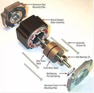
BLDC motors are usually composed of the following main components:
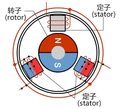
A Rotor is usually composed of a permanent magnet, which generates a magnetic field.
Stator: Part fixed to the housing, usually consisting of a set of windings and magnets.
Sensor: Used to detect rotor position and speed for proper on-off control of current in the stator windings.
Control circuit: used to drive the motor, through the appropriate current control to make the motor rotation torque.
Power supply: The supply of current to a motor, usually a DC power supply.

DC motor (brush motor) operation diagram

Operation diagram of BLDC motor
2. Application field:
BLDC motors are widely used in many fields due to their high efficiency, high power density, low maintenance and reliability, including but not limited to:
Household appliances: such as washing machines, refrigerators, vacuum cleaners, etc.
Cars and vehicles: such as electric cars, electric bicycles, electric scooters, etc.
Aerospace: such as aircraft landing gear, auxiliary power systems, etc.
Industry: such as mechanical equipment, automated production lines, etc.
3. Working principle:
The working principle of the BLDC motor is based on the magnetic field interaction between the stator and rotor of the motor. BLDC motors are usually driven by electronic control, which works as follows:
Stator magnetic field generation: When a current passes through the stator winding, a magnetic field is generated.
Rotor magnetic field induction: The permanent magnet in the rotor senses the magnetic field generated by the stator, resulting in torque.
Electronic control: Through the electronic controller, according to the rotor position and speed information fed back by the sensor, the current of the stator winding is switched timely to maintain the rotation direction and speed.
Rotation: According to the instructions of the electronic controller, the current in the stator winding is switched according to the change of the rotor position in time, resulting in a rotating torque, so that the rotor rotates.
|
Disclaimer: This article is transferred from other platforms and does not represent the views and positions of this site. If there is any infringement or objection, please contact us to delete it. thank you! |


